
Preparation of Power Source and Weld Materials
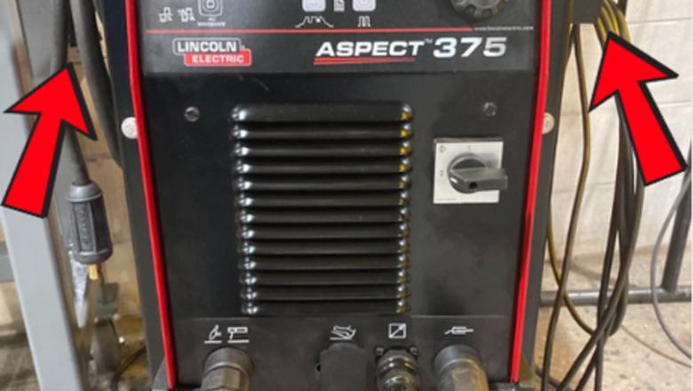
Uncoil welding connections and cables. Remove the variable amperage foot pedal from the side of the machine and uncoil the torch and ground connection. Connect the ground to the steel worktable. For this demonstration, all process variables will be set up using the Lincoln Aspect 375 Gas Tungsten Arc Welder. *See tip #1*
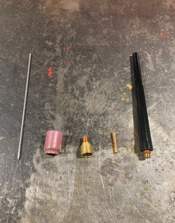
Locate the consumables for the torch. When acquiring all consumables, ensure they are meant for the same diameter tungsten. For tungsten selection, use a 3/32” ceriated or lanthanated tungsten, which is optimal for both aluminum and stainless steels. If consumables are not the same diameter, the fitment in the torch will be too loose and will not conduct an electric current. The necessary consumables that are in the photo from right to left include: tungsten electrode, shielding cup, gas lens, collet body, and back cap.
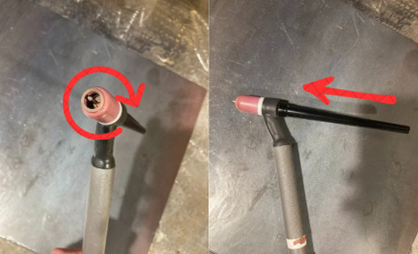
Assemble the torch. Screw the gas lens onto the front of the torch. Then take the tungsten and slide the collet on with the larger end of the collet towards the back. Then take the tungsten and collet and slide it through the back of the torch through the gas lens. Screw the back cap onto the rear of the torch and the shielding cup onto the front.
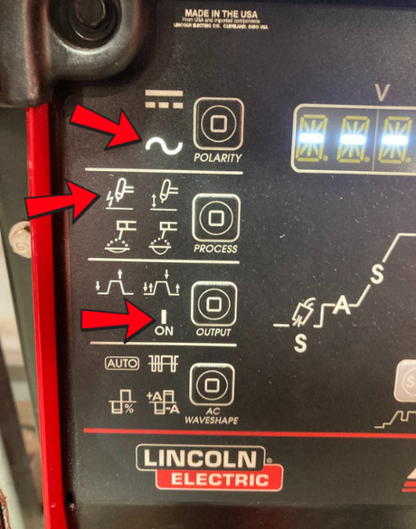
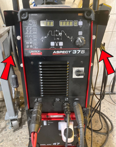
Adjust the weld process settings. Turn the welder on, then locate the buttons on the left-hand side of the welder. When selected, a light will be illuminated on that certain process. Using the attached photo, ensure the three lights match.
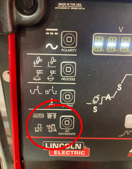
Adjust the background settings. Locate the bottom AC Waveshape button. Click it and use the main dial knob to set the following for AC aluminum Gas Tungsten Arc Welding. AC Waveshape Settings: Frequency - 150 Hz Balance - 80% Preflow - 2 seconds Postflow - autoAC frequency button.png
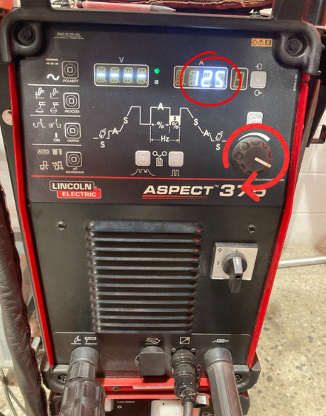
Set the amperage on the welder. Locate the dial amperage knob. Set the amperage by rotating the dial and watching the digital readout until it says 125 Amps. Rotating the dial clockwise will increase the amperage output, whereas rotating the dial counterclockwise will decrease the amperage output.
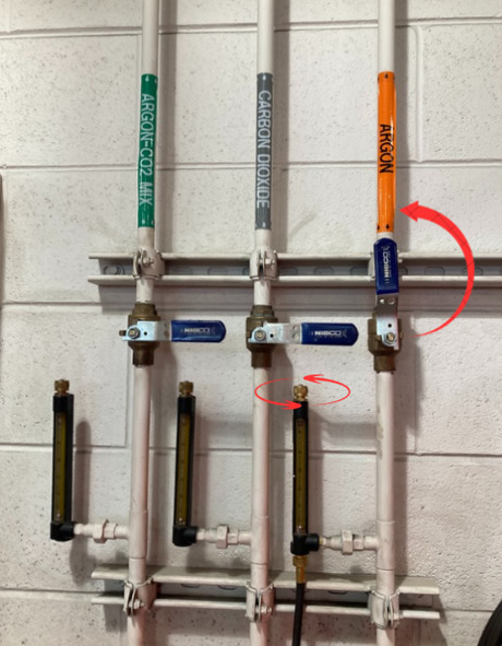
Turn on and adjust the shielding gas system. Acquire 100% Argon shielding gas and regulator. Rotate the valve so it is parallel with the pipe to allow gas to flow. Set the regulator to 25 CFH (Cubic feet per hour) by pressing the foot pedal and rotating the dial clockwise to increase CFH and counterclockwise to decrease CFH. Too little CFH will cause erratic weld arcs as well as weld profile discontinuities. Too much CFH will cause contamination and porosity due to high CFH turbulence.
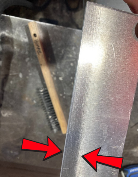
Clean the aluminum coupons. Acquire 1/8” x 2” x 6” aluminum coupons and a stainless-steel wire brush. Brush the edges of both coupons to remove aluminum oxide, which will increase weldability. Weldability is the material's ability to withstand being manipulated by welding processes. Therefore, the easier it is to weld, the higher the weldability. *See tip #2*
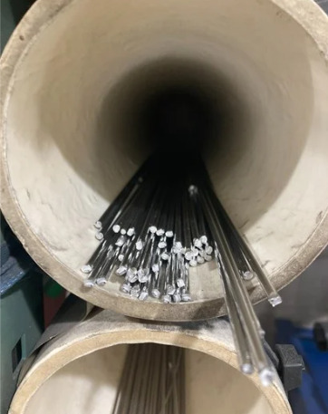
Locate the correct filler metal to use. Since this demonstration will be using 1/8” thick aluminum coupons, use a 1/8” ER4043 filler rod. A general rule of thumb is that the diameter of the filler rod should never exceed the thickness of the base material. This is because the base metal must melt faster than the filler, or else there will be improper fusion.
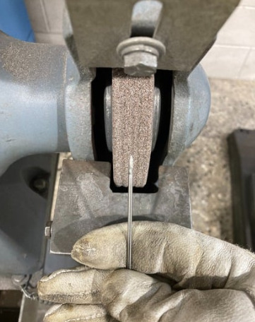
Prepare tungsten for welding aluminum. Acquire a 300-grit tungsten bench grinder. Rotate the tungsten when sharpening and make a 45-degree angle on the tungsten tip. Dip the tungsten in water after two full rotations to prevent the tungsten from becoming hot. Repeat the process until the tungsten is sharp to a point. *See tip #3*
Procedure To Weld Flat (1G) Corner Joint
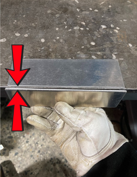
Set up the 1G corner joint. Create a 90-degree angle with aluminum coupons. Set the first coupon flat on the table. Then push that same coupon so it protrudes roughly 1/4" off the tabletop. After that, place the second coupon in one's left hand. Use the edge of the table to assist the process and push plates together/apart to create a 1/16” root opening. A root opening is the intentional gap that is placed between the coupons to ensure melt-through penetration is established.
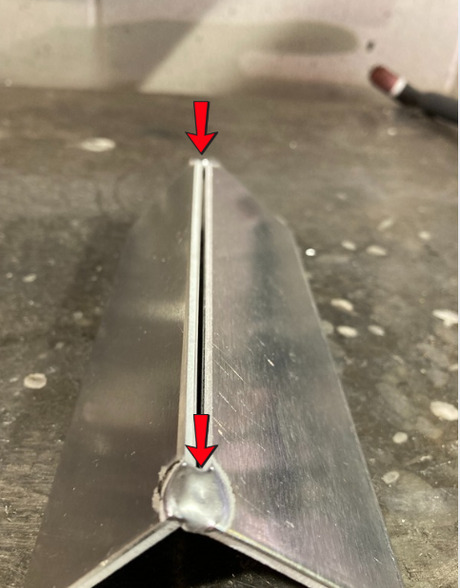
Tack the corner joint together. Acquire and hold the torch in the joint and press the foot pedal to the floor. Watch the material heat up and join the two pieces with a molten puddle. To end the arc, release the foot pedal. After tacking one side, bend the other side of the aluminum corner joint to match the root openings and tack. *See tip 4*
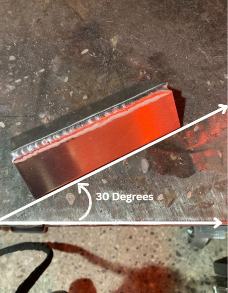
Create a comfortable welding position. Position the corner joint so that it is angled slightly away from the table edge; anywhere from 0-30 degrees is sufficient. This will allow one to see the full length of the joint and be in a more comfortable position when welding. This is called having proper "sight lines".
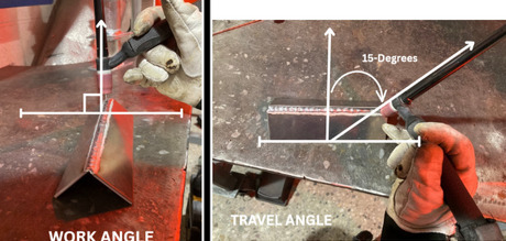
Establish work and travel angles. Before initiating the arc, adjust the torch grip so that a 90-degree work angle and a 15-degree travel angle are established. A work angle is the relation from the electrode to the base surface. Thus, if a protractor is laid flat on the table transverse to the weld joint, at 90 degrees is where the work angle should be. The same goes for travel angle, which is the angle at which the torch is traveling in relation to the joint. Thus, if a protractor is laid flat on the table running parallel with the joint, the electrode must be at 15 degrees from 90. *See tip 5*
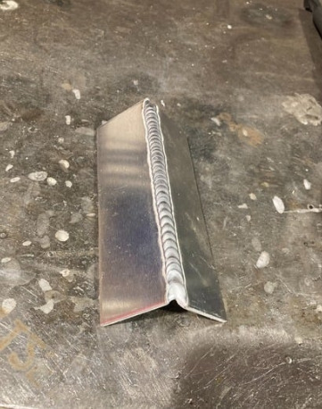
Weld the corner joint. Ensure to watch the puddle start to suck down into the joint due to gravity. Then begin to dab filler metal in the joint and watch the puddle rise from the addition of filler. Repeat the process of dabbing the filler until the end of the joint. By letting the puddle suck down, ensure that you have full melt-through penetration, which is standard by most structural codes.
Cleanup and Deburr
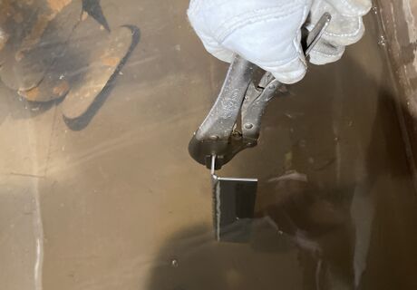
Quench the corner joint. Acquire a pair of channel lock pliers. Adjust the screw on the end of the channel locks for the 1/8” thick coupons and clamp-weld specimen. Quench the workpiece in water to cool it down to room temperature. Ensure the welded specimen is cool to the touch.
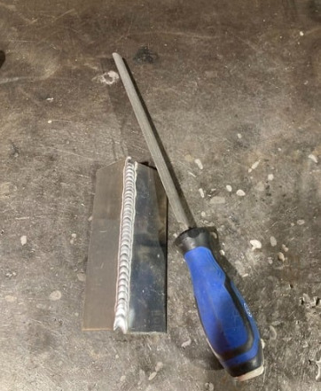
Deburr the corner joint. Acquire a metal hand file. Deburr any sharp edges or corners so the joint is smooth to the touch. This will prevent any possibility of injury or cuts. Ensure once completed with deburring to remove welding gloves and run hands over the joint as a general precaution for others' safety.
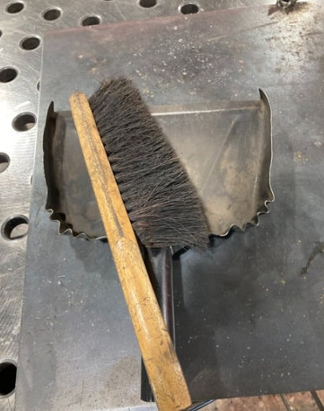
Clean up the work area. Turn off the welder, coil up the torch and ground leads, remove consumables from the torch, and rotate the gas valve so it is perpendicular to the pipe. After all is complete, acquire a broom as well as a dustpan and remove any debris acquired on the work surface. Dump all loose welding debris in a scrap bin.


Comments
0 comment