
Mounting the LED Strip
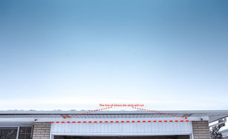
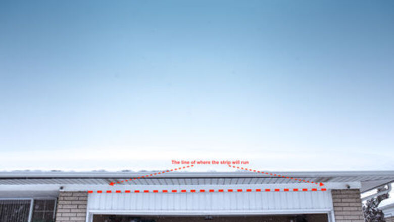
Determine where you want your LED strip for the lights to have the best effect. Note the line of where the strip will run.
Measure the length of the areas where you want to install your lights. Draw a plan for calculations. One roll of LED strip is 5 meters in length, so you can cut the strip into a desire length or find the areas that equals to strip length.
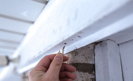
Screw the cup hooks along the eaves. Space them every 6 inches. Drill pilot holes to make it easier to screw them in.IMG_9647.jpg
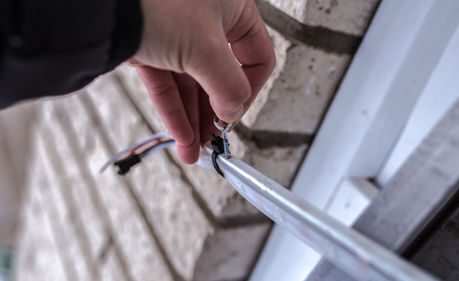
Screw the crew eyes into the plastic strip. Space them every 6 inches. Make sure spacing within each cup hooks and between each crew eyes are equal.
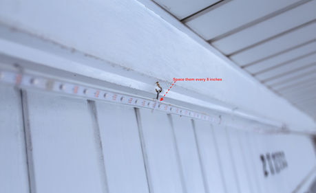
Space the zip ties. Place zip ties every 8 inches to attach the LED strips to the plastic strips.
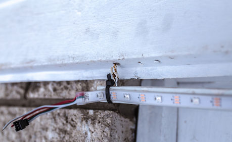
Hang the LED strip to the eaves by matching up crew eyes with cup hooks.
Wiring the LED Strip
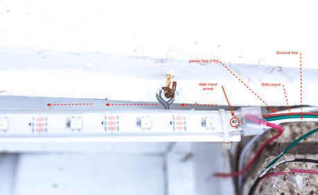
Examine the LED strip. Each end of the strip will have three wires. Ground wire (GND); Data signal input (Din); Power wire (+5V). Note the data line flow direction on the strip.
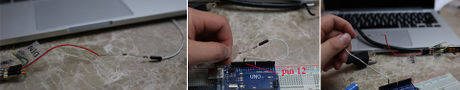
Connect the data input wire. Connect the 470 Ohm resistor in series with the LED strip’s data signal wire (green). This resistor helps prevent spikes on the data line that can damage the first LED of the strip. Connect a jumper from pin 12 on the Arduino to another end of the resistor.
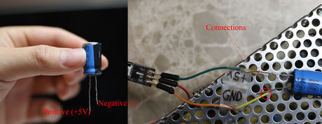
Connect the short negative (-) leg of the 1000 uF capacitor to the ground wire (GND) and longer positive (+) leg to power wire (+5V) of the LED strip.
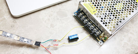
Connect the LED strip to the power supply. Cut the led strip cable into desirable length. Only cut the part that has a piece of plastic in it (and no wires visible). If you cut where the connection is, the lights won't work. Use a wire to connect the power wire (+5V) on the LED strip to the +V port on the power supply. Connect the LED strip’s ground wire (GND) to the –V (COM) port of the power supply. Unscrew the screws on the power supply’s ports to insert wires and then tighten up the screws.
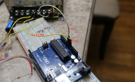
Power the Arduino. Grab a long jumper wire, and connect Vin pin on your Arduino to power supply’s +V port. Grab a jumper wire, and connect GND pin on your Arduino to ground wire of the led strip.
Make sure none of the wires are shorting. The LEDs on the strip are very sensitive and can become bad. Secure all open wire connections with electrical tape.Schemvatic.jpg
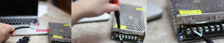
Connect the extension cord to the power supply. Connect green wire to ⏚ Connect black wire to L Connect white wire to N
Installing the Arduino Software
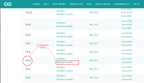
Download and install Arduino IDE 1.6.5. You can download it free from Arduino's website. The newer Arduino IDE version is not applicable for this project, because the code can’t compile. Double click on the downloaded file and follow program installation guide.
Disconnect the Arduino Uno from LED strip. Make sure there is no connection between the Arduino board and light strip.
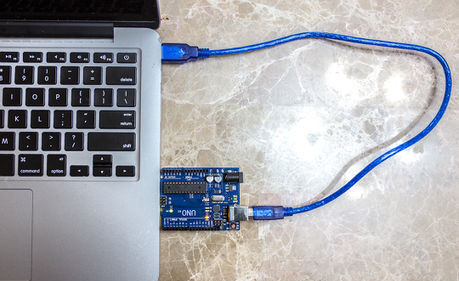
Connect Arduino Uno board to your computer via a USB cable.
Installing PololuLedStrip Library and Uploading the Codes
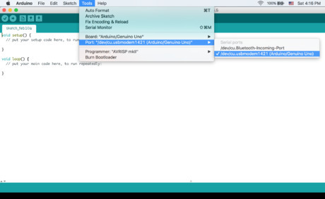
Go back to the Arduino IDE. Choose the correct USB port for Arduino IDE so it can connect to your board. Click on Tools then navigate to Port and then click on correct port (For Windows users: COM3, COM2...). If no COM ports appear in the menu, try a different USB port, or a reboot of your computer.
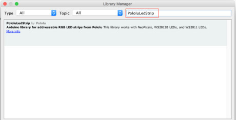
Install the Pololu Library. Click on "Sketch" and navigate to "Include Library" and then "Manage Libraries". Click on search bar and type in PololuLedStrip Screen Shot 2018 02 07 at 1.57.58 PM.pngLocate PololuLedStrip by Pololu and click the install button.
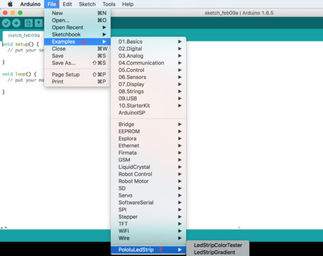
Upload the codes to the Arduino Board. Click on "File" then "Examples" then "PololuLedStrip." Lastly double click on LedStripXmas. The Arduino IDE will open a new window contains codes for this project.Screen Shot 2018 02 09 at 10.11.36 PM.png Change the number of LEDs in the codes. Enter 150, this led strip has 150 LEDs.Screen Shot 2018 02 09 at 10.27.33 PM.png Click upload button and check the status bar. The IDE will compile your code and if no errors are found. If you get errors, check your code.
Unplug the Arduino Board from computer.
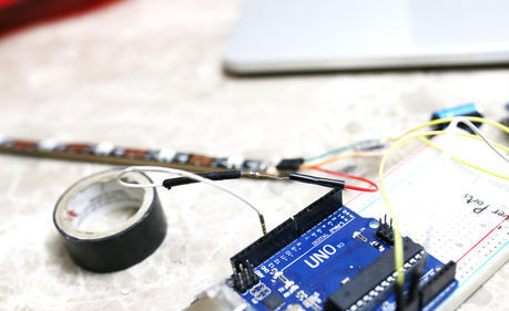
Reconnect it back to the LED strip. Connect pin 12 on Arduino to the LED strip's data wire. Connect power jumper wire (+5v) to pin Vin and ground jumper wire to GND on Arduino.
Testing
Plug the extension cord into the nearest outlet.
Check status light (yellow) on the power supply. The light should be stay on constantly.
Finished!


Comments
0 comment