
views
Getting Started

Check your local electrical codes and schedule inspections. Several inspections and permits are required for most residential construction projects, especially when it involves electrical work. To make sure you're up to code, you may need to schedule a temporary service inspection, a rough-in inspection, and a final inspection. This needs to be done whether you're doing it yourself or hiring an electrician. Depending on where you live, you may be able to do the inspection yourself if you live in a single-family home. The National Electrical Code requires all GFCIs within 5 feet (1.5 m) of the floor to be tamper-resistant and clearly marked. Outdoor GFCIs must also be weather resistant and clearly marked with the letters "WR," even if it has a weather cover. In some areas, you may need a GFCI due to nearby water fixtures. Check your local wiring codes to see if a three-prong GFCI is an acceptable replacement for a non-grounded two-prong receptacle. There are acceptable installation procedures for a non-grounded GFCI, usually involving putting a sticker on the receptacle cover stating "No Equipment Ground." The GFCI does not, itself, require any ground connection for proper operation. If your home was wired "to code" initially, there is generally no legal requirement to upgrade to grounded outlets or GFCI (or even AFCI) outlets unless other work is being done that exposes the wiring. Insurance or other safety concerns may, however, outweigh meeting only the minimum code requirements.
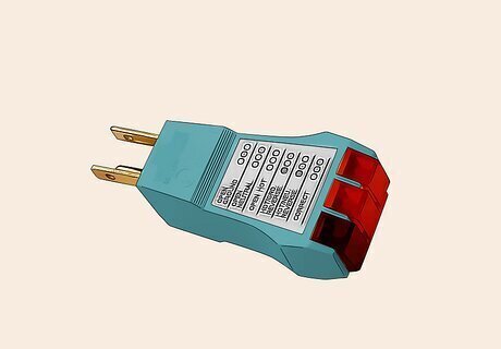
Purchase a circuit tester at a local home repair store. A circuit tester plugs into the receptacle and has several light combinations to indicate the different problems a receptacle may have. If you're going to ground a receptacle, it's an important tool to have. You can purchase these at any home repair store. One model has a button to test GFCI receptacles by shutting off the outlet if it detects any excess current. It's a little more money but a better buy to verify the GFCI is also grounded. For instance, the tester can tell you if the outlet is missing a ground or even if the wiring is reversed.
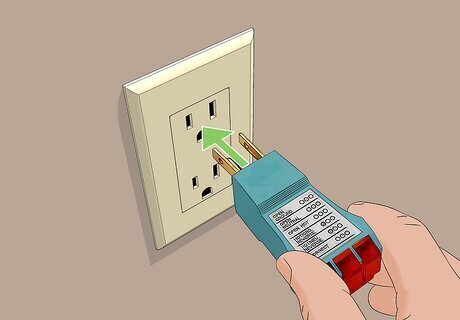
Test the receptacles in your home. To use the circuit tester, simply plug it into each receptacle and look at the indicator lights. If the lights indicate the receptacle is not grounded properly, mark the cover with a piece of masking tape. Move on to the next receptacle. Most such testers are designed with three prongs: hot, neutral and ground. If your receptacle has only two prongs, use a multimeter by placing one lead in the hot port on the receptacle and the other on the the metal outlet box or the metal of the plate screw. If the meter reads around 120 V, then the box is grounded. If you don’t get a voltage reading, then the box isn’t grounded. Make sure your circuit tester is working before you start by plugging it into a receptacle that you know works. Do not try to fix more than one receptacle at a time. Unless you are sure of your work, it's better to check them one at a time. This may involve turning the electrical circuit breaker on and off many times while you work.
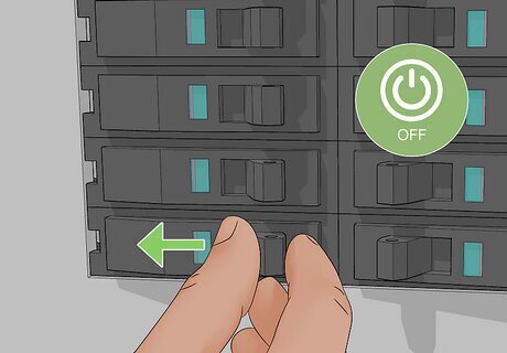
Turn off the power at the main electrical box. Either turn off the circuit breaker that controls the receptacles to the specific room or turn off the main switch for the whole house. If you only turn off the breaker, retest the receptacle with the circuit tester to ensure it's the correct one. Some "circuit identifier" devices automatically confirm you have switched off the proper circuit because the "tone" unit plugged into the receptacle stops signaling when its circuit is off. Be aware that some duplex (double) receptacles may be internally "split" so that one part is switched separately from the other, such as for floor lamps. You may find a receptacle is still "hot" in one and not in the other if the switch is off but the breaker is still on. You should test BOTH outlets of a duplex receptacle unless you already know how it's wired, i.e., after you open the box and pull it out.
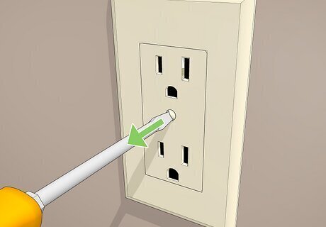
Remove the cover plate of the receptacle. For the most part, cover plates will be attached with flathead screws, which means you should be able to easily remove them with a small, flathead screwdriver. If paint or wallpaper is in the way slightly, you might need to carefully cut around the receptacle with a utility knife to keep the wallpaper from tearing and making the wall look raggedy.
Examining the Receptacle
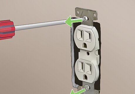
Remove the receptacle. Unscrew the mounting screws located at the top and bottom of the receptacle. You may need to cut the painted edge or plaster and pry it loose. Carefully pull out the receptacle from the box as far as the wires allow and locate the green grounding screw near the bottom of the receptacle. Locate the grounding wire, if applicable. Oftentimes, the grounding wire is bare copper. The grounding wire may also be green if it comes from a factory-assembled device. A metal box might also be grounded via conduit or metal-sheathed cable.
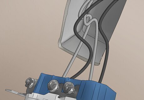
Examine the receptacle and the wiring. If you have three wires in the box (black, white, and copper), you will need to attach or tighten the grounding wire. If you have only two wires and a 2-prong receptacle, you can attach a GFI or GFCI receptacle. This provides ground fault circuit interruption to the branch circuit and must be identified as "no equipment ground." If your older wiring only has two wires (black and white, with no grounding wire), the box is not grounded and you will have to replace the cable with the right number of conductors, including a black, white, and grounding wire, if you desire grounding (e.g., for reducing radio-frequency noise). GFCI receptacles will not protect sensitive electronics, but grounding wires will. In the United States, a separate ground wire may only be run to an existing receptacle to provide a Ground for a GFCI receptacle if the wires are installed following the National Electric Code (NEC). If you have a ground wire, usually a bare copper or green wire, in a cable or conduit arriving in the box, it may or may not be grounded, which means you should test that for ground. If you have one of those, you can hook it up to a grounded receptacle and use an ohmmeter to check for resistance. If the metal outlet box has little to no resistance, then it’s grounded. Metal conduit and many types of metal-sheathed cables also serve as proper grounding means, provided they have an unbroken "path" bonded to a proper grounding point. If you find very old wiring (black cloth around rubber-coated wiring), you may have to leave it alone and call an electrician to replace it properly. Simply moving it may have permanently damaged the insulation, making it unsafe to energize.
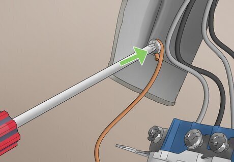
Secure the ground wire. Often the grounding wire is wrapped around the cable as it enters the box. In this case, you should pigtail all of the device grounds together and have one lead from the pigtail ground to the metal device fixture box and another lead used as a ground for the new grounding receptacle.
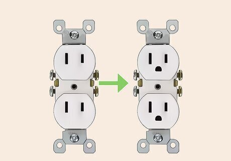
Install a new receptacle if necessary. If you don’t have a grounding conductor in the box, and you need an actual ground reference there, grounding that receptacle would require installing new wiring to code. Grounding a three-prong GFCI replacement for a two-prong receptacle is not always necessary. If you are going to use a GFCI to protect and control additional receptacles, with or without ground, you can use the cable and conductors that run to other receptacles that are in line (down the chain) from that GFCI. One GFCI will protect all of them if properly connected as "load" on the first GFCI. The load terminals on the GFCI are only used if you’re trying to protect other receptacles with that GFCI. There are two terminals on the receptacle that are normally used: hot and neutral. The ground terminal is not actually used by the GFCI but must be marked "No equipment ground" on each protected receptacle if it is not connected to a grounding conductor.
Grounding the Receptacle
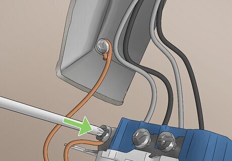
Attach the grounding wire to the grounding terminal. If the grounding wire has become loose or disconnected, loop the grounding wire over the green terminal screw and tighten with a Philips or flathead screwdriver. Make a loop at the end of the copper wire with a pair of needle-nose pliers. This secures the wire onto the screw. Be sure to place the loop of the wire on the terminal screw so that when you tighten the screw, the loop is tightened and not pushed off the terminal. On a GFCI receptacle you would connect to the two "Line" terminals. Only the downstream receptacles would be connected to the "load" terminals of a GFCI. Check the connection of the other wires as well. The black wire should be securely fastened to the brass terminal, which is marked "Hot," and the white wire to the silver terminal, which is labeled "Neutral." On a polarized receptacle, or a grounded receptacle, the larger slot is neutral (white wire) and the smaller slot is hot (black wire). While you're there, make sure any other connections in the box are tight, including wire nuts holding all wires securely, tucked out of the way, and any clips or screws are tight.
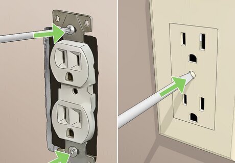
Secure the receptacle. Wrap the receptacle with electrical tape, covering the terminals, and push the receptacle back into the box, folding the wires carefully and making sure the bare copper wire is not near the "hot" terminals. Tighten with the mounting screws. Replace the cover plate and tighten securely, but not hard enough to crack the plastic.
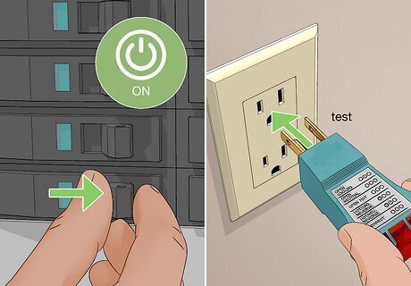
Turn the power back on. Retest with the circuit tester to be sure you now have a correctly grounded receptacle. If it is a GFCI receptacle, press the reset button. Plug in a device, switch it on, press the test button on the receptacle (shutting off the device) and then the reset button (turning it back on), to confirm its correct operation. If you have provided a ground to the receptacle, you may also use your external tester with a GFCI test button to test the GFCI function. Note that most external GFCI testers (i.e., 3-prong plug-in with its own GFCI "test" button) will NOT trip an ungrounded GFCI, but the internal GFCI test circuit in a receptacle will verify that the basic function works, even with no ground connected to it. A more sophisticated tester with an additional grounding wire of its own would make a better test in such circumstances.





Comments
0 comment